MRI testing to assess the MRI safety and compatibility of your products
We offer a wide range of tests for evaluating the safety of medical devices in the MRI environment, here is a non-exhaustive list:
ASTM tests
ASTM F2052Measurement of the displacement force generated by the static magnetic field
A device may be subject to an induced displacement force when exposed to the strong static magnetic field of an MR scanner.
The ASTM F2052 standarddescribes an evaluation method based on measuring the deflection angle of a device suspended from the end of a non-metallic string as it is brought near the MRI magnet. This angle is used to calculate the induced Force on the device.
The intensity of the force depends on the magnetic susceptibility and the volume of the materials. Within a product range, the worst-case scenario corresponds to the device that combines the largest volume with the highest magnetic susceptibility. Identifying the worst-case can be more complex when multiple materials are involved.
The results are interpreted by comparing the calculated force to a maximum acceptable threshold.
ASTM F2213Measurement of the torque generated by the static magnetic field
Medical devices made of magnetic or ferromagnetic materials may experience an induced magnetic torque when exposed to the magnetic field of an MRI scanner.
This torque tends to align the device along the field lines, similar to how a compass needle aligns with the Earth’s magnetic field.
The induced torque depends on the magnetic properties of the material, as well as its volume and shape.
The ASTM F2213 standard describes several test methods for quantifying or estimating magnetic torque. All these methods rely on observing or measuring the tendency of the device to orient itself when placed in the static magnetic field of an MRI scanner in various orientations.
The results are interpreted by comparing the measured torque to an acceptance criterion, which by default is the torque generated by the weight of the device.
ASTM F2182 Measurement of the Radio Frequency induced heating
In MRI, the heating induced by radiofrequencies (RF) results from the absorption of RF energy by conductive materials. This phenomenon depends on numerous parameters: the geometry, dimensions, and materials of the device, as well as MRI conditions (position, orientation, type of MRI system, sequences used, etc.).
The ASTM F2182 standard provides a method for evaluating such heating in passive implantable devices. It involves:
– Immersing the device in a gel that simulates the electrical and thermal properties of the human body,
– Measuring the temperature rise at potential hot spots around the device, and at a reference point located away from the device,
– Repeating the measurements without the device to determine the local RF exposure at the measurement points.
The results help characterize the thermal response of the implant in a standardized environment, but do not always directly predict heating under clinical conditions. Complementary numerical simulations are often necessary to identify potential hot spots and assess expected in-vivo heating.
ASTM F2119Evaluation of the image artifacts generated by the presence of the device
The presence of a device within the field of view of an MRI image can cause artifacts (i.e., distort the image). The ASTM F2119 standard defines a method for characterizing these artifacts for passive implants. This method involves acquiring two sets of MRI images under strictly identical conditions:
-A first set without the presence of the device (reference image)
-A second set with the device
Quantitative comparison of these images allows for determining the extent of the generated artifacts. The results are expressed in terms of the maximum distance between the edge of the implant and the edge of the artifact.
ISO/TS 10974
Clause 8Assessment of radiofrequency heating
In MRI, heating induced by radiofrequency (RF) fields results from the absorption of electromagnetic energy by conductive structures within the device. This phenomenon depends on multiple parameters, including the geometry, dimensions, and materials of the device, as well as MRI conditions (position, orientation, system type, and MRI sequences used).
ISO/TS 10974 Clause 8 provides a framework for evaluating RF-induced heating in active implantable medical devices. It combines experimental measurements performed in tissue-simulating media with numerical simulations to assess a wider range of exposure conditions.
The results are used to estimate temperature rise under clinically relevant conditions and to identify potential worst-case scenarios.
Clause 9Assessment of gradient field heating
Time-varying gradient magnetic fields in MRI can induce electrical currents in conductive components, which may lead to additional heating. This effect depends on the rate of change of the magnetic field, as well as the geometry, position, orientation and electrical properties of the device.
ISO/TS 10974 Clause 9 describes methods for assessing gradient field-induced heating, using analytical approaches, experimental measurements, or numerical simulations.
The results help determine whether this contribution is significant and whether it must be considered in the overall thermal safety assessment.
Clause 10Evaluation of vibrations
Rapid switching of gradient magnetic fields can generate forces on conductive or magnetic components of a device, resulting in mechanical vibrations.
These vibrations may lead to patient discomfort or mechanical stress on the device and the surrounding tissues.
Clause 10 of ISO/TS 10974 provides methods for evaluating the impact of such vibrations on the device functionality.
Clause 11Measurement of the displacement force induced by the static magnetic field
A device may be subject to an induced displacement force when exposed to the strong static magnetic field of an MR scanner.
ISO/TS 10974 Clause 11 describes an evaluation approach based on ASTM F2052.
The results are interpreted by comparing the calculated force to defined acceptance criteria.
Clause 12Measurement of the magnetic torque induced by the static magnetic field
Medical devices made of magnetic or ferromagnetic materials may experience an induced magnetic torque when exposed to the static magnetic field of an MRI scanner. This torque tends to align the device along the field lines.
ISO/TS 10974 Clause 12 describes evaluation methods consistent with ASTM F2213, based on observing or measuring the tendency of the device to rotate when placed in the magnetic field in different orientations.
The results are interpreted by comparing the measured torque to an acceptance criterion, typically related to the torque generated by the weight of the device.
Clause 13 Assessment of gradient field induced currents
Time-varying gradient fields in MRI can induce electrical currents in conductive structures such as leads or elongated components. These currents may contribute to heating or cause unintended electrical stimulation.
ISO/TS 10974 Clause 13 provides experimental methods for assessing induced currents and their potential impacts on stimulation signals, taking into account device configuration and exposure conditions.
The results are used to evaluate potential risks associated with these induced currents.
Clause 14 Assessment of malfunctions due to the static magnetic field
The static magnetic field of an MRI scanner may affect the operation of active implantable devices, for example by influencing magnet-sensitive components or altering sensor behavior.
ISO/TS 10974 Clause 14 describes methods for evaluating such effects by exposing the device to representative static magnetic field conditions.
The results are used to determine whether the device maintains its intended performance and safety.
Clause 15Assessment of radio frequency induced malfunctions
RF fields used in MRI may interfere with the normal operation of active devices by inducing voltages or affecting electronic circuits.
ISO/TS 10974, Clause 15 provides methods for evaluating RF-induced malfunctions in active implants through controlled exposure to representative RF fields.
The results are used to identify any functional disturbances, unintended mode changes, or loss of performance.
Clause 16Assessment of gradient field induced malfunctions
Switching gradient fields can induce voltages in device circuitry, which may lead to malfunctions or unintended behavior in active implants.
ISO/TS 10974, Clause 16 describes evaluation methods to assess these effects under representative gradient field conditions.
The results help determine whether the device continues to function as intended during or after MRI exposure.
Clause 17Assessment of the combined field effects (possibility to monitor implant activity)
In MRI, devices are exposed simultaneously to static, gradient, and RF fields. The combined effects of these fields may differ from those observed when each field is considered separately.
ISO/TS 10974, Clause 17, provides methods for evaluating device performance under exposure conditions similar to those encountered during a clinical examination, including monitoring device activity during exposure when relevant.
The results are used to assess whether interactions between fields lead to unexpected effects or safety concerns.
Clause 18Evaluation of the image artifacts generated by the presence of the device (18.3.9)
The presence of a device during an MRI examination can cause artifacts on MRI images (i.e., distort the image).
ISO/TS 10974 Clause 18.3.9 describes methods for characterizing these artifacts by acquiring images with and without the device under identical conditions and comparing them quantitatively.
The results are expressed in terms of the spatial extent of the artifact relative to the device.
Other tests
Measurement of magnet demagnetization according to AAMI CI86
Extraction of the magnet from a cochlear implant according to AAMI CI86
Specific test methods defined in ISO14708 and AAMI PC76
Each device is unique, and our expertise allows us to adapt to most situations. We design and carry out tailor-made tests to meet any particular demand, especially when the normative methods are not directly applicable (non-implantable devices for example). So contact us to discuss your project.
Why choose Healtis?
Quality commitment
Our quality policy allows us to guarantee the reliability of our test results and the conformity of our practices with the normative requirements.
HEALTIS is ISO/IEC 17025 accredited (accreditation N° 1-6320, scope available on www.cofrac.fr).
Benefit from our support!
You will be in touch with one of our experts from the first contact. They will communicate with you all of the necessary information to understand the basis of MRI Safety assessment for medical devices and the relevant regulatory framework. They will take into account your needs to bring you an adapted response to your inquiry.
Attend Testing In person!
Throughout the realization of your project we guarantee a clear communication and strong support. You will have all the information you need to understand our work and if you wish, may attend the realization of your tests.
Healtis Gives you confidence in your testing strategy
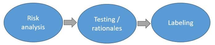
The typical MRI safety and compatibility assessment study will look something like this:
Risk analysis: The first step of any MRI testing activity should be a detailed risk analysis. This involves both determining the possible risks to the patient, but also identifying any possible malfunction that can be induced. This step also involves drafting the strategy for project. Certain risks can be accessed via different methods or may be treated via scientific arguments with written rationale. So at this stage, determining the most adapted strategy to assess the device is key.
Testing / Rationale Writing: The second step is to either perform device testing or draft scientific arguments via a written rationale to address all the possible risks and malfunctions identified in step 1. At this stage, just prior to testing, for multiconfigurational devices, worst-cases are identified. Any simulations that are necessary to identify worst-case are performed, often in parallel to other device testing. At this step all test reports or rationales are objective and independent.
Labeling: In this third and final step, all test results and rationales are analysed, and based on the totality of the results an MRI label is determined. In almost all cases, the label will be an MRI Conditional label. During this phase, the conditions for which the device can be introduced in the MRI environment are determined.
On average, how long should an MRI study take?
The entire MRI safety and compatibility assessment workflow can take as little as 3-4 weeks to complete, and as long as 3-4 months depending on the complexity of the project. Typically, wholly implanted passive medical devices are on the order of 3-4 weeks while active implantable medical devices (AIMD) are on the order of 3-4 months. Often, the timeline is influenced by the ability of the device manufacturer to supply CAD for numerical simulations or test objects for testing.
How many devices do I need to supply for testing?
The number of samples required for a test campaign depends on the characteristics of the medical device. It is sometimes possible to carry out several tests on the same sample, particularly if the first tests have had no influence on the sample’s physical properties, especially its electrical and magnetic properties. It is generally preferable to have one sample for each test.
How are tests performed?
Your tests will be performed on clinical MRIs, by qualified engineers, PhDs or test technicians.
Our instruments are selected or designed by our team of experts to meet all the constraints of the MRI environment and the normative requirements. All instruments are qualified, calibrated and regularly monitored.
We additionally have available a probe for measuring signals during an MRI exam; this allows, for example, to monitor the activity of an active implant in the MRI environment during an MRI exam (pacemaker, neurostimulator, etc.)
Does Healtis have experience testing my particular type of device?
For more than 10 years, HEALTIS has performed safety and MRI compatibility tests on a large number of implantable and non-implantable devices. Which, for the most part, have been introduced to the US, European, or Asian markets. More than 500 trials have already been conducted in our laboratory for clients from all backgrounds and a variety of devices. Here are some examples of devices we have tested: